Q1K EEG-eyetracking Lab Specification
This section describes the hardware and software, and lab configurations for the Q1K EEG-eyetracking lab. Provided that you have access to the same hardware and software, you can use this documentation to replicate the Q1K EEG-eyetracking lab setup.
Overview
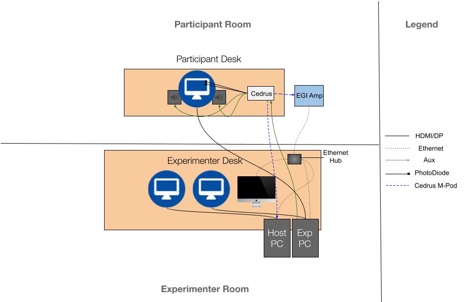
Simultaneously recorded eye tracking (ET) and EEG require the two recordings to be synchronized in time. In the Q1K set-up, the ET and EEG are recorded on separate computers, but both systems receive the same trigger signal (i.e. events) from the stimulus computer, which is used to synchronize the two recordings during analysis.
The Q1k lab uses Magstim (EGI) EEG equipment and SR Research ET equipment. The EGI system is comprised of a Mac computer running Net Station 5, and a Net Amps 400 EEG amplifier. The SR Research system is comprised of a PC running the experiment software (hereafter referred to as the “Display PC”), and an Eyelink 1000 Plus eye tracker (which itself is comprised of a standalone PC, which we call the “Host PC”, and the eye tracking lens on a participant display). A Cedrus Stimtracker is used to send timestamps of stimulus events to both the EEG and ET systems, which can be used to synchronize the EEG and Eyetrcking signals during analysis.
Hardware
Hardware |
Software |
Specifications |
|---|---|---|
EGI Net Amps 400 |
||
EGI 129ch Hydrocel Nets |
||
Cedrus Stimtracker Quad |
|
|
iMac |
Net Station 5 Acquisition software |
|
SR Research Eyetracker “Host” PC |
|
|
Experiment software Ultra Performance PC (“Display PC”) |
|
|
ASUS VG248QE, 24” Participant Display |
|
Communication Across systems
The Display PC, Host PC, iMac (Net Station Acquisition), and EEG amplifier are all connected to an ethernet hub via ethernet cables, which allows them to communicate with each other and share events. The specific communication protocol is handled under the hood by the Magstim and SR software, as these two companies maintain an ongoing collaboration to ensure that their systems are compatible.
Cedrus Stimtracker
The Cedrus Stimtracker is a device that measures the actual times of stimulus presentation (both visual and auditory) and sends this information back to the EEG and eyetracking acquisition systems. This information is critical for synchronizing the EEG and ET data, as the cedrus events regarding stimulus onsets are used to synchronize the EEG and ET data. Note that for the Q1K tasks, either a Stimtracker Duo or a Stimtracker Quad can be used.
Configuring the Stimtracker
The Stimtracker can be configured via a combination of the knobs on the device itself, and settings for each M-Pod and Trigger that can be set via the the Xidon 2 software. The knobs on the device are used to set the sensitivity of each line (Light sensor 1, Light sensor 2, Audio left, Audio right), and the Xidon 2 software can be used to specify further device settings, such as hold on/off times, and to set specific settings for each M-Pod connected to the Stimtracker.
Trigger |
Placement |
Specifications |
|---|---|---|
Light Sensor 1 (photodiode 1) |
|
|
Light Sensor 2 (photodiode 2) |
|
|
Audio left |
|
|
Audio right |
|
|
M-Pod Parallel port |
|
|
M-Pod EGI |
|
|
Important
It’s crucial that the M-POD for EGI is set to use Negative logic. See this blog post.
Configuring the Eyetracker to accept Stimtracker events
By default, the Eyelink will not write Stimtracker events (sent via parallel port)
to the EDF file. To enable this, you must add extra lines of code to the FINAL.ini
file on eyelink file browser partition of the Host PC. This file is located at
/ELCL/EXE/FINAL.ini.Please see this
post
and follow the instructions to add accept DATA Register events to the EDF file, which should specify
to add the following block of code to the end of the aforementioned FINAL.ini file:
write_ioport 0xA 0x20
input_data_ports  = 8
input_data_masks = 0xFF
create_button 1 8 0x01 0
create_button 2 8 0x02 0
create_button 3 8 0x04 0
create_button 4 8 0x08 0
create_button 5 8 0x10 0
create_button 6 8 0x20 0
create_button 7 8 0x40 0
create_button 8 8 0x80 0
You may also refer to this post for more information on using TTL events with Eyelink systems.
DIN Event codes for Stimtracker
The Stimtracker sends events to the EEG and ET systems via the parallel port. The specific event codes that are associatedd with pulses from Light sensor 1 Light Sensor 2, Audio, etc, are displayed below:
Trigger |
EGI DIN |
EYELINK DIN |
|---|---|---|
Light Sensor 1 (photodiode 1) |
DIN2 |
2 |
Light Sensor 2 (photodiode 2) |
DIN3 |
4 |
Light Sensors 1 & 2 (photodiode 1 & 2) |
DIN2, DIN3 |
? |
Audio left |
DIN4 |
8 |
Audio right |
DIN4 |
8 |